
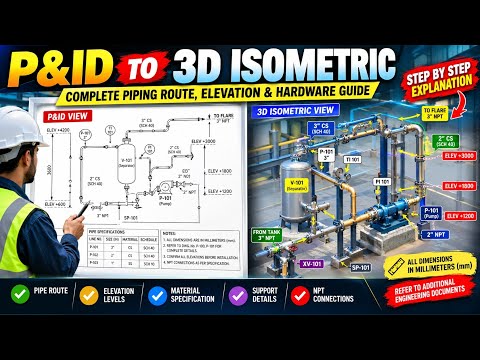
In the complex world of industrial design, the journey from a conceptual idea to a physical pipeline is both a science and an art. Central to this process are two critical documents: the Piping and Instrumentation Diagram (P&ID) and the 3D isometric drawing. Understanding how to bridge the gap between these two is a fundamental skill for any professional working with modern Engineering CAD tools.
Decoding the P&ID: The Project's Brain
A P&ID serves as the functional "roadmap" of a processing plant. It is not drawn to scale; instead, it uses a standardized set of symbols and lines to represent the relationship between piping, instrumentation, and system equipment. It details everything from flow directions and valve types to safety regulators. Think of the P&ID as the logical blueprint that tells the system what to do, without necessarily defining exactly where each pipe will sit in physical space.
The Leap to 3D Isometric Drawings
While the P&ID handles the logic, the 3D isometric drawing handles the reality. Unlike the schematic nature of a P&ID, an isometric drawing provides a three-dimensional representation of a single pipe run. It includes precise measurements, technical angles, and specific material specifications.
This is where Engineering CAD becomes indispensable. By using specialized software, engineers can translate 2D symbols into a 3D environment that accounts for structural constraints, gravity, and spatial efficiency. This transition ensures that what works on a 2D map will actually fit within the confines of a physical facility.
Why the Transition Matters
Mastering the transition from P&ID to 3D is about more than just digital drafting; it is about project accuracy and safety. When working within a robust Engineering CAD framework, designers can perform "clash detection." This process ensures that a new pipe doesn't attempt to occupy the same space as a steel beam or an electrical conduit. Furthermore, these digital models can automatically generate accurate Bills of Materials (BOMs), significantly reducing material waste and procurement errors.
Conclusion
The evolution from 2D schematics to 3D models has revolutionized the field of piping engineering. By understanding the functional logic of a P&ID and the spatial precision of an isometric drawing, engineers can ensure that complex industrial systems are built safely, efficiently, and on schedule. Whether you are a student or a seasoned professional, staying updated on these digital modeling techniques is the key to success in modern industrial design.


