
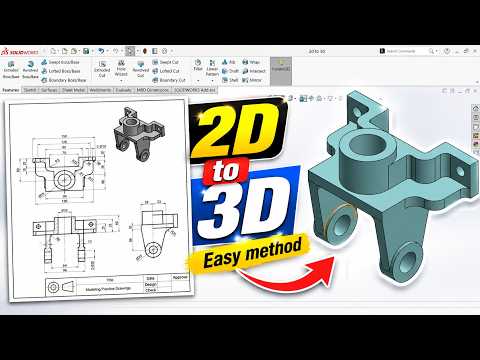
Transitioning legacy design files or flat engineering sketches into modern parametric CAD software can significantly streamline your engineering workflow. If you work with legacy blueprints, DXF files, or PDF reference sheets, knowing how to transform a 2D drawing into a fully functional 3D model in SOLIDWORKS is an essential skill for engineers, product designers, and draftspeople alike.
Why Convert Flat Drawings to 3D Parametric Models?
While flat technical blueprints remain standard for manufacturing documentation, 3D models offer unmatched benefits in visualization, mass property calculations, interference detection, and digital prototyping. By converting your flat geometric layouts, you gain the ability to perform structural simulations, generate dynamic assembly views, and export clean files for modern production methods like CNC machining and 3D printing.
Step-by-Step Method to Convert Your Design
SOLIDWORKS provides flexible, user-friendly tools designed to make this conversion fast and accurate. Here is a practical workflow to turn your flat sketches into solid geometry:
- Import Your Flat Layout: Open a new SOLIDWORKS part file and import your DXF or DWG geometry directly onto a designated work plane (Front, Top, or Right).
- Clean Up the Sketch: Check that all imported lines form closed, continuous contours. Delete redundant construction lines and fix broken endpoints so the software can properly interpret the profile.
- Align Orthographic Views: If your 2D drawing includes multiple perspectives (such as front, top, and side views), align each view onto its corresponding orthographic plane to construct an accurate 3D reference framework.
- Apply Parametric Features: Select the key profiles and use fundamental features such as Extruded Boss/Base, Revolved Boss, or Extruded Cut. Reference dimensions directly from your imported geometry to define exact extrude depths.
- Add Final Specifications: Finish your model by adding secondary details like fillets, chamfers, threads, and hole patterns based on the original design specifications.
Conclusion
Converting a legacy 2D drawing into a detailed 3D CAD model doesn't have to be complex or time-consuming. By leveraging basic sketch tools and feature extrusions in SOLIDWORKS, you can efficiently upgrade static flat graphics into fully flexible, production-ready 3D components. Try this streamlined approach on your next project to enhance your design accuracy and speed!


