
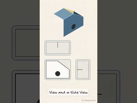
Modern engineering relies heavily on 3D computer-aided design (CAD) software to visualize and prototype products. However, when it comes to manufacturing, machining, and quality control, technical blueprints remain the universal industry standard. Bridging the gap between digital concepts and real-world production requires converting complex three-dimensional models into precise technical documents.
Why Convert 3D Models into Engineering Blueprints?
While a 3D model shows what a component looks like, a detailed 2D drawing provides the exact technical specifications a machinist needs to fabricate it. These documents serve as precise instructional guides and legal technical contracts. They specify critical dimensions, geometric tolerances, surface finishes, and material requirements that a standard 3D visual render cannot clearly convey.
Essential Views in Technical Drafting
To accurately represent a three-dimensional object on a flat sheet of paper or screen, engineers utilize standard orthographic projection techniques. A comprehensive 2D drawing typically includes the following views:
- Front View: Represents the primary face and main features of the component.
- Top View: Displays the depth and top features directly aligned above the front view.
- Side View (Profile): Provides additional profile dimensions, detailing height and depth relationships.
- Isometric View: A 3D pictorial view that helps technicians quickly visualize the finished part.
By combining these standard views with section cuts and detailed callouts, engineers ensure no internal or external feature is overlooked during fabrication.
Core Components of a Professional Blueprint
Creating a functional 2D drawing involves far more than projecting lines onto a page. Every professional engineering document must include critical annotations and metadata:
- Dimensions and Tolerances: Clearly defined measurements paired with geometric dimensioning and tolerancing (GD&T) to indicate acceptable variations in size.
- Title Block: Positioned at the corner of the sheet, it contains project information such as part numbers, revision history, material specifications, author details, and scale.
- Standardized Symbols: Uses specific line types (such as centerlines and hidden lines) along with surface finish and welding symbols to communicate manufacturing requirements clearly.
Conclusion
Translating a 3D object into a 2D engineering format is a fundamental skill for engineers, drafters, and product designers. By mastering orthographic projections and standardized drafting rules, you ensure seamless communication between design teams and the shop floor, converting abstract digital concepts into high-precision physical reality.


