
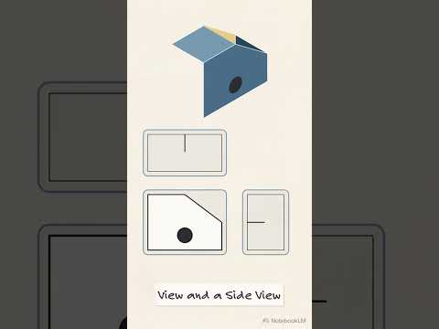
In the world of engineering and manufacturing, visualization is everything. While 3D models offer a realistic spatial view of an object, actual production processes often rely on precise technical blueprints to turn concepts into reality. Translating a complex physical or digital 3D object into a precise 2D drawing is a foundational skill that bridges the gap between design and manufacturing.
Why Is a 2D Drawing Essential in Engineering?
Even with the rise of modern 3D printing and advanced CAD software, standard technical documentation still depends on flat, two-dimensional representations. While a 3D visual render shows the overall shape of a component, a standardized 2D drawing conveys critical manufacturing instructions that renders cannot easily display.
Key details provided in engineering drawings include: - Exact Tolerances: Defining the acceptable limits of variation in dimensions. - Surface Finish Requirements: Specifying how smooth or rough specific faces must be. - Geometric Dimensioning & Tolerancing (GD&T): Ensuring complex features fit together properly during assembly. - Material and Hardware Callouts: Detailing the exact metals, plastics, or fasteners required.
Understanding Orthographic Projection
The standard method used to convert a 3D object into a flat technical sheet is known as orthographic projection. This technique projects the object's features perpendicularly onto standard 2D planes, allowing designers to view the part without perspective distortion.
A complete engineering draft usually consists of three primary orthographic views: 1. Front View: Captures the main profile and primary features of the part. 2. Top View: Reveals the depth and overhead feature layout. 3. Side View: Displays vertical relationships and profile details.
Auxiliary views, section cuts, and isometric views are often added to reveal hidden internal geometries and simplify complex shapes for the machinist.
Modern CAD Workflows
Generating a professional 2D drawing from a 3D model has become remarkably efficient with modern software like SolidWorks, Autodesk Fusion 360, or AutoCAD. These platforms maintain parametric links between the 3D model and the 2D draft. If an engineer modifies a feature in the 3D environment, the dimensions and views on the drafting sheet update automatically, reducing errors and saving crucial design time.
Conclusion
Mastering the transition from a 3D object to a two-dimensional visual representation is essential for clear technical communication. By applying consistent projection standards and clear dimensioning, engineers ensure their ideas are built accurately, every single time.


