
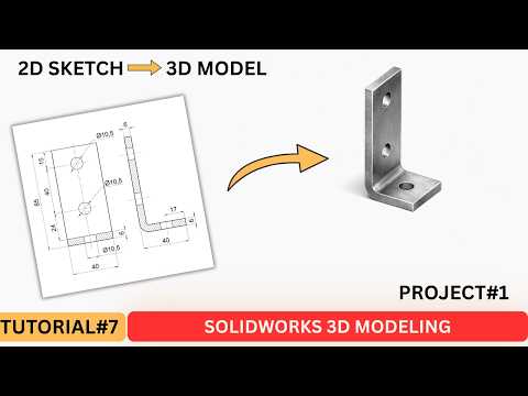
Moving from paper blueprints or flat digital files to fully dynamic 3D CAD models is an essential skill for any engineer, designer, or CAD enthusiast. If you are working with a technical 2D drawing of a mechanical component—like a standard mounting bracket—converting that flat layout into a solid 3D part in SolidWorks might seem daunting at first. However, by mastering a few fundamental features, you can streamline your design workflow effortlessly.
In this guide, we will break down the simple process of transforming flat engineering blueprints into accurate 3D CAD models using core SolidWorks techniques.
Step 1: Analyzing the Blueprint and Setting Up Your Base Sketch
Before jumping into feature creation, take a moment to carefully review your source file. Identify the primary view—usually the front or top view—that contains the most defining geometry. In SolidWorks, select the appropriate reference plane (Front, Top, or Right) and begin recreating the main outline.
To build a solid foundation, ensure every dimension from your original 2D drawing is accurately translated into fully defined sketch entities. Utilizing geometric relations like concentricity, parallelism, and symmetry will keep your design intent intact and easy to modify later.
Step 2: Adding Depth with Extruded Boss/Base
Once your primary sketch is complete and fully defined, it’s time to bring it to life. Select the Extruded Boss/Base tool to give your sketch physical thickness. For a standard mounting bracket, extruding the primary profile establishes the core solid body. Choose the appropriate end condition (such as Mid Plane or Blind) to simplify future feature placements.
Step 3: Refining Features with Extruded Cuts
A mounting bracket is rarely just a solid block; it requires functional features like bolt holes, mounting slots, or chamfers. Create secondary sketches directly on the planar faces of your new 3D body to define these features. Applying the Extruded Cut tool allows you to remove material cleanly, matching the exact specifications detailed in your 2D drawing.
Final Thoughts
Transforming flat blueprints into production-ready 3D models comes down to structured steps and consistent practice. By mastering core operations like Extrude Boss and Extrude Cut, you will soon convert even the most complex technical drawings into detailed, fully editable 3D geometry with total confidence.


