
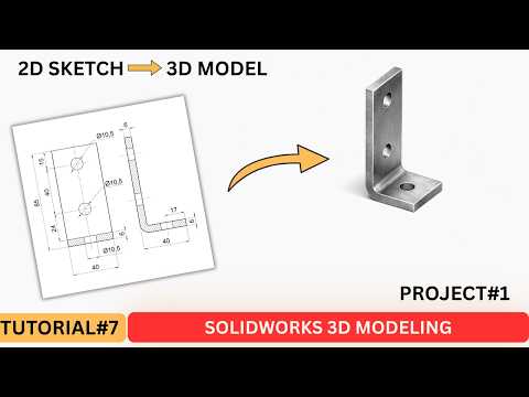
Transitioning from technical blueprints to dynamic 3D CAD models is a fundamental skill for modern engineers, product designers, and CAD hobbyists. In computer-aided design, translating a flat 2D drawing into a precise 3D model allows you to visualize, analyze, and manufacture components with complete accuracy.
In this tutorial guide, we focus on a practical engineering project: modeling a robust mounting bracket in SolidWorks using essential features like Extrude Boss/Base and Extruded Cut.
Step 1: Analyzing the Technical Blueprint
Before opening your CAD software, take a moment to carefully review your source 2D drawing. Identify the primary views—such as front, top, and side views—and note key dimensions, hole centerlines, and material thickness. Understanding the design intent beforehand prevents costly dimensioning errors during the sketching phase.
Step 2: Creating the Base Sketch and Extrusion
- Select the Sketch Plane: Open a new part document in SolidWorks and choose an appropriate plane (such as the Front Plane) that aligns best with the main profile of your bracket.
- Draft the Base Geometry: Use basic geometry tools like lines, arcs, and rectangles to construct the outer boundary of the mounting bracket.
- Apply Smart Dimensions: Add precise constraints and dimensions matching the blueprint specifications until the sketch is fully defined.
- Extrude the Profile: Convert your 2D geometry into a solid 3D block using the Extrude Boss/Base tool.
Step 3: Feature Refinement with Extruded Cuts
Mounting brackets require precise cutouts, mounting holes, and slots to function within an assembly. - Select a Surface: Click on the flat surface of your 3D base where feature cuts are needed and start a new sketch. - Locate Hole Centers: Reference your original 2D drawing to position circles or slots accurately using Smart Dimensions. - Execute Extruded Cut: Use the Extruded Cut tool—setting the end condition to "Through All"—to pierce through the material cleanly.
Conclusion
Mastering the workflow of converting engineering blueprints into solid geometry is essential for successful mechanical design and manufacturing. With practice, you will develop the speed and confidence needed to build complex CAD assemblies from scratch. Pick up your next design sheet and turn your concepts into 3D reality today!


