
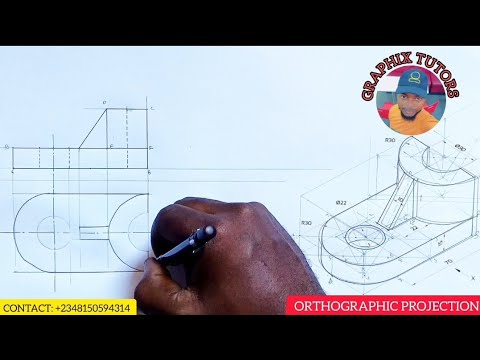
In the worlds of engineering, architecture, and manufacturing, the ability to translate a physical three-dimensional object onto a flat surface is a critical skill. Whether you are designing a complex mechanical engine or a simple household item, mastering the art of creating an accurate 2D drawing from a 3D object is essential for clear communication.
The primary technique behind this process is called Orthographic Projection. In this guide, we will break down what orthographic projection is, why it matters, and how you can apply it to your technical drafting workflow.
What is Orthographic Projection?
Orthographic projection is a method of representing a three-dimensional object using a series of two-dimensional views. Unlike perspective drawings—which mimic how the human eye sees depth—orthographic views remove perspective distortion. This means that parallel lines remain parallel, and measurements stay true to scale across every view.
To achieve this, technical designers project light rays perpendicularly from the object onto a flat plane. Typically, an orthographic technical document includes three standard views: * Front View: Shows the height and width of the object. * Top View (Plan View): Placed directly above or below the front view, showing the width and depth. * Side View (Profile View): Placed to the side, displaying the height and depth.
Why Manufacturing Depends on 2D Representation
While modern 3D CAD models are fantastic for visualization, a precise 2D drawing remains the ultimate blueprint for the manufacturing floor. 3D renders can hide critical details, obscure dimensions, or create visual ambiguity due to angles.
By flattening the object into standard two-dimensional views, engineers can clearly specify exact dimensions, geometric tolerances, surface finishes, and material callouts. This eliminates guesswork, reduces expensive errors during production, and ensures that manufacturers worldwide can recreate the part with exact precision.
Basic Steps to Convert 3D Models into a 2D Format
- Choose the Principal View: Select the side of the 3D object that reveals the most detail and features as your primary Front View.
- Align Your Views: Project construction lines horizontally and vertically from your front view to establish the positions for the top and side views.
- Incorporate Line Types: Use solid object lines for visible edges, dashed hidden lines for features concealed behind surfaces, and centerlines for symmetrical features or hole centers.
- Add Dimensions: Place clear measurements between the views without cluttering the drawing.
By mastering orthographic projection, you bridge the gap between creative visual design and practical manufacturing, turning your complex 3D concepts into a professional 2D drawing that anyone in production can easily interpret.


