
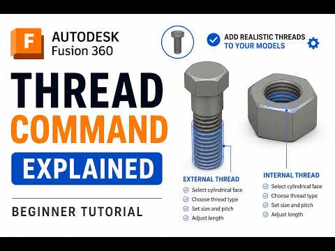
Whether you are designing a custom bolt, a mechanical assembly, or a 3D-printed enclosure, knowing how to generate precise threads is a vital skill to master in Fusion360. While manual modeling is possible, the dedicated Thread command streamlines the process, ensuring your components fit together perfectly every time.
Understanding the Thread Tool
The Thread command is located under the "Create" menu. Unlike drawing a coil manually, this tool allows you to apply standardized thread profiles to existing cylindrical faces. To get started, you simply need a hole for internal threads or a cylinder for external threads. Once the face is selected, the software automatically detects the diameter and suggests appropriate thread standards, such as ISO Metric or ANSI Unified Screw Threads.
Cosmetic vs. Modeled Threads
One of the most important decisions you will make in Fusion360 is choosing between "Cosmetic" and "Modeled" threads. * Cosmetic Threads: These appear as a texture on your model. They are lightweight and ideal for complex assemblies where you only need to indicate that a thread exists for a technical drawing. * Modeled Threads: By checking the "Modeled" box, the software cuts the actual geometry into the 3D shape. This is essential if you plan to 3D print your parts or perform a high-fidelity render. However, be aware that modeled threads increase the computational load on your computer.
Customizing Your Specifications
Precision is key in engineering. Within the Thread dialog box, you can adjust the thread class, direction (right-hand or left-hand), and pitch. If you are working on a project that requires a loose or tight fit, adjusting the "Class" setting can help you achieve the desired tolerance.
Best Practices for Internal and External Threads
When creating internal threads (like inside a nut), ensure your initial hole diameter is correct for the tap size you intend to use. For external threads (like on a bolt), starting with a chamfer on the edge of your cylinder can make the threading process look more professional and help with real-world assembly.
By mastering these simple steps within Fusion360, you can transition from basic shapes to complex, functional mechanical parts with ease. Experiment with different standards and always double-check your "Modeled" settings before exporting for manufacture!


